| C H A P T E R 12 |
|
Creating a Microsoft Windows and Motif Application |
This chapter shows you how to produce the simple application shown in FIGURE 12-1 on both Motif and Microsoft Windows. In addition, Single Sourcing at the end of this chapter looks at the how you might share callback files between UNIX and Microsoft Windows.
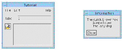
This tutorial shows you how to put together a main application window and a sub-dialog. As well as building the user interface, it uses links, callbacks and sets resources, including pixmaps. It even shows you how to pop up a menu in a drawing area. All of this will be ported to Microsoft Windows.
It is assumed that you are familiar with the basic use of X-Designer--creating hierarchies, setting names and resources and so on. If you are not, try following the main tutorial which starts in .
1. Start X-Designer in Microsoft Windows mode.
See Starting in Microsoft Windows Mode if you are not sure how.
2. Start with a Session Shell. Add a form to it and put a menubar, a button, a scrolled window, a label and a text field inside the form.
This hierarchy is shown in FIGURE 12-2.
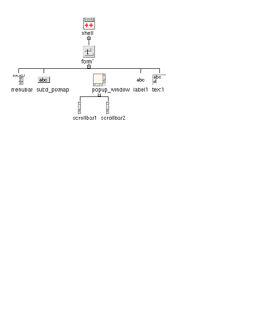
3. Name the shell "shell", the menubar "menubar", the scrolledwindow "popup_window" and the button "subd_pixmap".
You do not need to name any other widgets--names of the type [widget-class][number] (e.g. "button1") are the default names assigned by X-Designer.
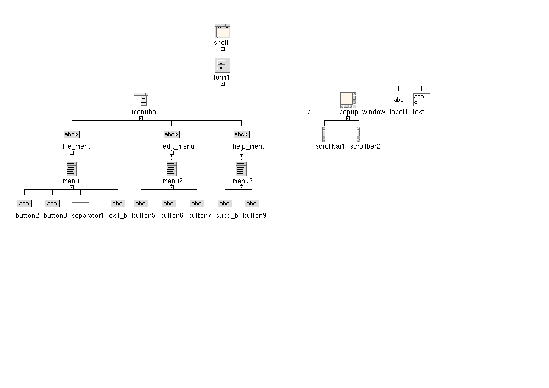
4. To the menubar, add three cascade buttons. Name them "file_menu, "edit_menu" and "help_menu" respectively.
5. To the "file_menu" cascade button, add a menu. Add two buttons, a separator and another button to this menu.
6. Name the last button added to the menu "exit_b".
7. To the "edit_menu" cascade button, add a menu. Add three buttons to this menu.
8. To the "help_menu" cascade button, add a menu. Add two buttons to this menu, naming the first one "subd_b".
The completed hierarchy for the menubar is shown in FIGURE 12-3.
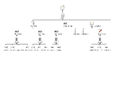
9. To the "popup_window" scrolled window, add a drawing area. Name it "draw_area".
10. To the drawing area, add a popup menu naming it "popup". Add three buttons to the popup menu.
The completed scrolled window hierarchy is shown in FIGURE 12-4.
11. Use the Form layout editor to adjust the layout of the widgets inside the form so that the dynamic display looks as shown in FIGURE 12-5.
You will need to move the widgets to the right place and specify attachments. If you are not sure how to do this, read Chapter 4 first.
Although the Form widget will not be generated into the Microsoft Windows code (we have not made it a C++ class), attachments and positions are calculated and handled by X-Designer in the generated code. In this way the resize behavior will be preserved. See Manager Widgets and Layout for more details.
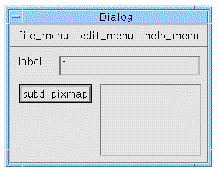
12. Save your design into a file named MyWinApp.xd.
13. Add another shell to your design--this time a dialog shell. Name it "sub_shell".
14. Add a form to the shell and name it "sub_form".
15. Add a label and a button to the form. Name the button "close_b".
The completed hierarchy for this sub-dialog is shown in FIGURE 12-6.
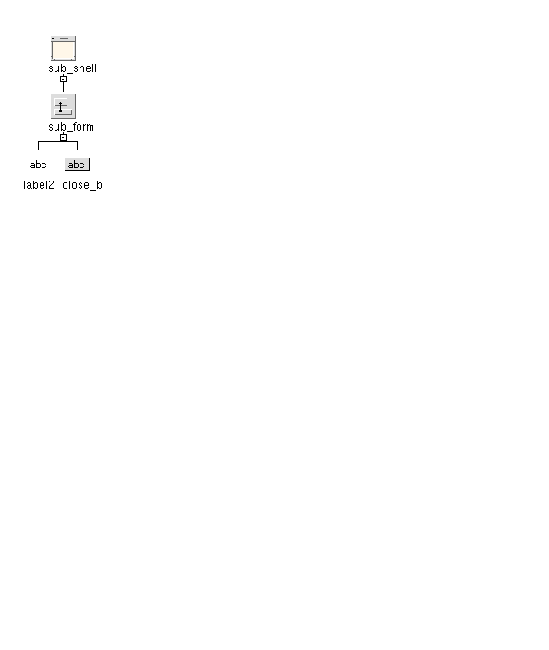
16. Use the Form Layout Editor to layout the widgets so that the button is at the bottom of the dialog and the label grows when the dialog is resized, as shown in FIGURE 12-7.
You will need to move the widgets to the right place and specify attachments. To make the label grow, for example, attach the bottom of the label to the top of the button and attach all other edges to the sides of the form. If you are not sure how to do this, read Chapter 4 first.

Here we shall add a callback method for the close button which will close the sub-dialog, and a callback method on exit_b in the file menu of the main application shell.
1. Select the close button, close_b.
2. Display the Callbacks dialog and select the Activate callback from the list of callback types.
3. Check that the option menu underneath the list of defined callbacks says "Method name".
You will be generating C++ so you need to check that you are adding methods.
4. Type DoClose into the text box and press the "Add" button.
5. Close the Callbacks dialog.
6. Select the shell named "shell" in the window holding area.
7. Select the button named "exit_b" underneath the file menu.
8. Display the Callbacks dialog and select the Activate callback from the list of callback types.
9. Check that the option menu underneath the list of defined callbacks says "Method name".
10. Type DoExit into the text box and press the "Add" button.
11. Close the Callbacks dialog.
You are going to add a link to display the sub-dialog from the main window. X-Designer is able to generate code to implement links on both Motif and Microsoft Windows. See Using Links for restrictions on Microsoft Windows which should be taken into account when creating links. Read Links if you are not sure how to set up links in a dialog.
1. Select "subd_b" in the menu called "help_menu" in the main application shell "shell" and display the Edit Links dialog.
Do this either by pressing the button on the toolbar or by selecting "Edit Links" from the Widget menu. in shows you where to find the Edit Links button on the toolbar.
Note that the Add button is pink when a menu button is selected as the destination widget. Show, Hide, Manage and Unmanage links are only effective for menu buttons on Motif; Enable and Disable links are effective on menu buttons in both Motif and Microsoft Windows. However, the menu button currently selected is not the destination widget for this exercise.
2. Select "sub_shell" in the window holding area.
The text box labelled "Widget" in the Links dialog now contains the name of the about dialog shell, "sub_shell".
3. Select the "Show" link in the Links dialog and press the "Add" button to add the Show link to "sub_shell".
4. Close the Edit Links dialog.
You are now going to add the same link from "subd_pixmap" in the main application shell.
5. Go back to the main application shell, "shell".
Select the shell from the window holding area.
6. Select "subd_pixmap" and display the Edit Links dialog again.
You need to redisplay the dialog so that the selected widget is the "source" widget. Otherwise, it is a "destination" widget.
7. Select "sub_shell" in the window holding area again.
8. Select the "Show" link in the Links dialog and press the "Add" button to add the Show link to "sub_shell".
9. Close the Links dialog and save the design.
Adding a popup menu to a DrawingArea widget is useful whichever language you intend to generate. The next stage of the tutorial shows you how to do this. If you intend to generate Motif 1.2 code, you will have to write a small amount of extra code as popup menus are not automatically supported versions of Motif earlier than Motif 2. If, however, you intend to generate Motif 2.1 code, you do not need to add any code as your popup menu is handled automatically by Motif.
If you intend to generate Motif 1.2 code for this design, you will have to add a callback so that you can add your own code for popping up a menu. Remember that you do not need to add this callback if you are going to generate Motif 2 code so skip to Popup Callback for Windows.
Motif and Microsoft Windows have different ways of popping up a menu so your code will have to be different for each platform. You will add the code to popup the menu later in the tutorial.
1. Select "draw_area" from inside the ScrolledWindow, "popup_window", in the main application shell.
2. Display the Callbacks dialog.
3. Select "Input" from the list of callback types and add a callback method called DoInput.
The Input callback type is marked with an asterisk (*), indicating that this callback will have no effect on Microsoft Windows.
4. Close the Callbacks dialog.
Whether you are generating Motif 1.2 or Motif 2 code, you need to set up a callback to display the popup menu on Windows.
1. Display the DrawingArea resource panel, shown in FIGURE 12-8.
The quickest way to do this is to double-click over the drawing area.
The Motif XP library does not attempt to emulate the Microsoft Windows drawing or input model, hence the list of Microsoft Windows target message handlers.
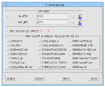
2. Set the OnRButtonDown toggle, press "Apply" and close the resource panel.
This will generate an appropriate Microsoft Windows message handler, which will be called in response to the corresponding Microsoft Windows message, and a matching callback stub.
Filling in the Stubs of this chapter explains how to fill in the stubs to popup the menu.
X-Designer generates resource files for Motif and Microsoft Windows. Motif, however, allows a far greater range of control over its widgets. Although there are resources in Microsoft Windows, they are limited in comparison with Motif/X resources. Microsoft Windows resources are compiled into the executable file so, unlike Motif, changing a resource on Microsoft Windows means re-compiling the application.
In this example application, we have string, pixmap and keyboard resources. First of all, we shall set the strings of the labels, buttons and shells.
1. Select the form which is the child of the main application shell.
2. Display the form's resource panel.
3. Set the dialog title to "Tutorial" by typing into the text field labelled "Title".
4. Press "Apply" and then close the resource panel.
5. Display the resource panel of the "file_menu" cascade button and give it the label string "File". Press "Apply".
6. Do the same for the other two cascade buttons so that "edit_menu" displays the label "Edit" and "help_menu" displays the label "Help".
This is shown in FIGURE 12-9.
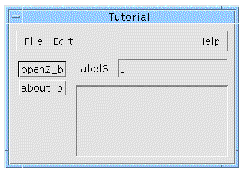
7. Set the labels of the buttons in "file_menu" to "New", "Open" and "Exit".
8. Set the labels of the buttons in "edit_menu" to "Cut", "Copy" and "Paste".
9. Set the labels of the buttons in "help_menu" to "About..." and "Help".
The three menus are shown in FIGURE 12-10.

10. Select the first button in the popup menu child of the drawing area and display its resource panel.
11. Set the button's label to "Cut".
12. Select each of the other two buttons in the popup menu and set their labels to "Copy" and "Paste" respectively.
13. Select the dialog shell "sub_shell" in the window holding area.
The design area now shows the hierarchy for this sub-dialog.
14. Select the label and display its resource panel.
15. Set the string of the label widget to display a few lines such as:
16. Center the string in the label by going to the "Settings" page of the resource panel and changing the "Alignment" option menu to "Center". Press "Apply".
17. Set the label of the button to "Close".
18. Set the title of the sub-dialog to "Information"
Do this by typing into the text box labelled "Title" in the resource panel of the Form which is the child of the shell. The completed dialog is shown in FIGURE 12-11.
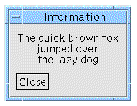
All of these labels are string resources. When you generate the code for the Motif version of your design you can decide whether the resources should go into the code or into the resource file. For the Microsoft Windows version all string resources are automatically generated into the source code.
If you are using pixmaps in your design, X-Designer automatically converts them to Windows bitmaps when you generate code. To illustrate this, you are going to give one of the buttons a pixmap label.
1. Select the button named "subd_pixmap" in the main application shell and display its resource panel.
2. Set the Type Resource of the buttons to Pixmap.
You can find this on the "Settings" page of the button resource panel.
3. Go to the "Display" page of the button resource panel and press the button labelled "Pixmap".
This displays the Pixmap Selector dialog.
4. In the Pixmap Selector dialog, either select an existing pixmap or press "Edit" to display the Pixmap Editor.
5. If you are creating a new pixmap in the Pixmap Editor, make sure that you type a name for it into the text field at the top and press "Bind". Close the Pixmap Editor.
6. In the Pixmap Selector dialog, press "Apply" so that the object name appears in the text field next to the button labelled "Pixmap" in the resource panel.
If you are not sure about creating and using pixmap objects, see Selecting a Pixmap.
7. When you press "Apply" in the resource panel, the pixmap you have specified is shown on the button.
Remember that filenames on MS-DOS (and Microsoft Windows) must be no longer than eight characters before the extension. X-Designer uses the name to which you bind the pixmap in the basename of the file in Microsoft Windows mode, so make sure that you have not specified a name longer than eight characters.
You have now finished the design of your application. The rest of this tutorial shows you how to generate code for the UNIX and for Microsoft Windows and how to build the application on each platform.
Now that you have designed the application user interface in X-Designer, you can generate the Motif and Microsoft Windows code. Having generated the code, you are then ready to build the two applications. Full instructions are provided in this section, including how to fill in the callback stubs.
For this tutorial, you need to generate two separate applications--one for Motif and one for Microsoft Windows. You should generate them into two separate directories to avoid such problems as overwriting and including the wrong header file. This tutorial does not exploit the possibilities of single sourcing, which are discussed in Single Sourcing.
1. Display the Generate dialog.
The filename fields are primed with names based on your X-Designer save file name.
2. Check that "C++ Motif XP" is the selected item from the "Language" option menu.
At the top of the dialog there is a text area where you can type the name of a base directory. All filenames are then relative to this directory. You can use the "Browse" button to find a directory.
3. Set the base directory to the area where you wish to generate your files.
Remember that you should generate the Motif XP and the Microsoft Windows MFC code into separate directories to avoid confusion.
4. Check that the "Generate" toggle is set for the "Code" file.
5. Open the Code Options dialog.
Press the button labelled "Options" next to the "Code" text box.
6. Set the "Include Header File" toggle
7. Make sure that the "Include Motif Header Files" toggle is set.
This saves your changes and closes the Code Options dialog.
9. Check that the "Generate" toggle next to "Externs" is set.
10. Set the "Generate" toggle next to the "Stubs" file.
11. Make sure that the "Generate" toggle next to the "Main Program" text box is set.
12. Display the Generate Options dialog.
Do this by pressing the button labelled "Options" at the bottom of the Generate dialog.
13. Check that the "Links" option menu is set to "Generated to Code".
14. Choose which Motif flavor you wish to generate.
This will depend on which version you have on your system. Check with your system administrator if you are not sure. By default, X-Designer generates code for Motif 2.1 as this is the most up-to-date version.
15. Change the "Strings" option menu to "Code" and check that all other resource types are set to "Code".
For the sake of simplicity, all the resource settings are going to be "hard-coded" for this tutorial. For a real application, you would normally generate them into a separate resource file.
This saves your changes and closes the Generate Options dialog.
17. Set the "Generate" toggle next to "Makefile".
18. Press "Generate" in the Generate dialog.
Your files are generated into the chosen directory.
This saves any settings in the Generate dialog.
You may have to edit the Makefile in order to access the Motif XP code, depending on how X-Designer has been installed and configured. Check that the XPCLASSLIBS and CCFLAGS definitions access the Motif XP library and include files. XDROOT is the path to the root of the X-Designer installation directory:
The steps to generate the code for Microsoft Windows are almost the same as for Motif. X-Designer remembers a different set of files for each flavor so you can use the toolbar flavor menus and code generation buttons once you have specified the name of the files for the different flavors.
Remember that, on the PC, a filename must be eight characters or less before the extension. Some IDEs, including Visual C++, complain if they encounter a source file containing C++ code which has been given only a .c extension. You can specify .cpp or .cxx.
1. Display the Generate dialog if you do not still have it open on the screen.
2. Check that "C++ Microsoft Windows MFC" is the selected item from the "Language" option menu.
3. Set the base directory at the top of the Generate dialog to a directory where you wish to generate your files.
Remember that you should generate the Motif XP and the Microsoft Windows MFC code into separate directories to avoid confusion.
4. Check that the "Generate" toggle next to the "Code" file is set.
5. Open the Code Options dialog.
Press the button labelled "Options" next to the "Code" text box.
6. Set the "Include Header File" toggle.
This saves your changes and closes the Code Options dialog.
8. Check that the "Generate" toggle is set for the "Externs" and "Stubs" files.
9. Make sure that the "Generate" toggle next to the "Main Program" text box is set.
10. Set the "Generate" toggle next to the "Microsoft Windows resources" file.
This file will contain the dialog templates. When this is set, X-Designer converts pixmaps into Windows bitmaps--one per file, as described in Pixmaps, Bitmaps and Icons.
11. Display the Generate Options dialog.
Press the button labelled "Options" at the bottom of the Generate dialog.
12. In the Generate Options dialog, check that the "Generate as Resources" toggle is set.
This makes X-Designer generate dialog templates which are Microsoft Windows resource files, as described in Generating Dialog Templates.
13. Check that the option menus for "Links" and all resources are set to "Generated to Code".
This saves your changes and closes the Generate Options dialog.
|
Note - You do not need to generate a makefile for the Microsoft Windows code because the files will be built in a different way. This is described in Compiling the Microsoft Windows Version. |
15. In the Generate dialog, press "Generate".
A message is displayed informing you that a bitmap file for your pixmap has been generated. The basename of the file is the name of the pixmap object.
When you generate MFC, you will find that extra files in addition to the code, stubs and header files are generated. These are:
If the generated code contains Japanese text, you need to post-process the code with a filter utility, xdtosj, which is provided as part of the X-Designer release, before transferring it to a PC. See Use of Japanese Font for more information.
You have two stubs files--one for MFC and one for Motif. Because you generated Motif XP code for your Motif application you could share some of the code. This is because X-Designer's XP library emulates some of the MFC for Motif. For simplicity and speed, however, this tutorial keeps the two separate. For more information on sharing the sources, see Single Sourcing.
There are two callbacks--one to exit the application and one to popup the menu from the drawing area. You should fill in the stubs as shown below:
There are callbacks in the Motif stubs file to match those in the MFC stubs file. Note, however, that you do not have a "DoInput" stub if you generated Motif 2 code as popup menus are handled automatically by Motif 2. You need to fill in the "DoInput" stub if you chose the "Motif 1.2" flavor in the Generate Options dialog.
Although the signature of the exit callback is the same for both platforms, the contents are different.
void shell_c::DoExit ( ) { exit (0); } void sub_shell_c::DoClose ( ) { this->ShowWindow(SW_HIDE); } void popup_window_c::DoInput ( ) { popup->TrackPopupMenu(0, 0, 0, this, NULL); } |
Having created the design, generated code and filled in the callback stubs, you are now ready to compile the application on both Motif and Microsoft Windows. After the brief section on building your application on Motif, there is a description of the steps you will need to take to build your application on Microsoft Windows.
Step-by-step instructions for building the application using Visual C++ on Microsoft Windows are given in Compiling the Microsoft Windows Version. However, you can build the generated code using any C++ development environment capable of integrating the Microsoft Foundation Classes, for example Symantec C++. Refer to Using Other Applications for general information about configuring Microsoft Windows-based C++ compilers to build the application.
All you need to do now is make the application by typing make at the command prompt in the directory where you generated the Motif code. Since you generated a Makefile, all the files in your application are automatically built.
Before running the application, be sure to arrange for the resource file to be read, as explained in Setting up the X Resource File.
If you are using Visual C++ Version 5 or later, compiling your application on your PC is very simple because X-Designer generates full Visual C++ project files for you. If you are using earlier versions of Visual C++ you will need to create the project. Although this is not so convenient, it does not take long and only needs to be done once. Instructions are given below for how to create the project in Visual C++ Version 4.0. If you are using a version of Visual C++ earlier than 4.0 and you need help on creating a project, contact X-Designer support. Using Other Applications gives you some tips on compiling your application if you are not using Visual C++.
Visual C++ is an IDE (Integrated Development Environment) to help you develop applications to run on Microsoft Windows. It comprises a number of tools, including a compiler, debugger and various editors. It is a useful tool for building, debugging and controlling the sources of an application. Note, however, that any changes you make to your code in Visual C++ cannot be taken back into X-Designer. Visual C++ uses the concept of a project to keep track of the files in your application. You always need a project when you use Visual C++. X-Designer generates the project files for you.
|
Note - PC-NFS, available from SunSoft, is a tool designed to make sharing files between your PC and your Solaris system easy. |
X-Designer generates fully configured project files for Visual C++ Version 5 and above. These are the files ending with a suffix of ".dsw" and ".dsp". Take both of these files to your PC along with all the MFC source files (this includes the code files, resource file, any bitmap files and header files).
1. On your PC, under Windows, double-click over the ".dsw" file generated by X-Designer.
Doing this instructs Visual C++ to open, with the project ready loaded.
2. Select "Build <projectname>.exe" from the Build menu.
If Visual C++ encounters any errors, these are displayed and the compiler stops compiling. You may now press F4 to ask Visual C++ to open the file containing the error and locate you at the relevant point in the file. Subsequent presses of F4 allow you to move through the list of errors, opening files as necessary. Double clicking on an error will also open the relevant file and move to the part of the file where the error was detected. The windows opened onto these files are full text editing windows. You can also view and edit a file in this way by selecting Open... from the File menu.
3. Once the application has built successfully, you can try it out. Select "Execute <projectname>.exe" from the Build menu.
If you are using Visual C++ Version 4, you cannot use the project files generated by X-Designer. The following takes you through the steps required to create the project.
1. Take all the MFC source files to your PC.
You do not need to take the ".dsp" and ".dsw" files as these are only relevant to Visual C++ Version 5 and above.
3. Select "New" from the File menu.
A list of new items which can be created is then displayed as shown below:
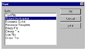
4. Select "Project Workspace" from the items list and Ok the dialog.
The New Project Workspace dialog is then displayed.
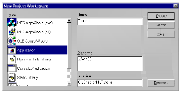
5. Select "Application" from the Type list and enter a name (such as "Tutorial") in the "Name" field.
6. Press the "Create" button to complete your actions.
You are then presented with the main Visual C++ dialog. Next, you must now populate your project with the files you wish to build.
7. Select "Files into project" from the Insert menu.
The following dialog is displayed:
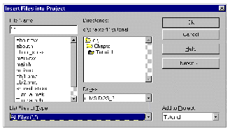
8. Locate the directory where you have placed the files you copied to the PC.
9. Highlight the files required by clicking on the first in the list then press shift and then click on the last of the files in the list.
10. Press the Ok button to add the selected files to the project.
11. Select the "Settings" option from the Build menu.
The Project Settings dialog is then displayed, as shown below:
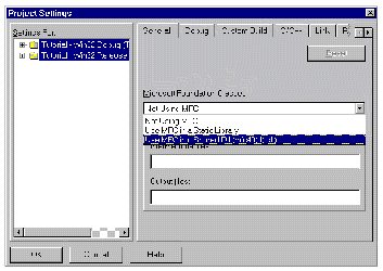
12. Select the "Use MFC in a Shared Dll..." option from the Microsoft Foundation Classes option menu as shown above and then Ok the dialog.
Finally, to build your application:
13. Select "Build Tutorial.exe" from the Build menu.
If Visual C++ encounters any errors, these are displayed and the compiler stops compiling. You may now press F4 to ask Visual C++ to open the file containing the error and locate you at the relevant point in the file. Subsequent presses of F4 allow you to move through the list of errors, opening files as necessary. Double clicking on an error will also open the relevant file and move to the part of the file where the error was detected. The windows opened onto these files are full text editing windows. You can also view and edit a file in this way by selecting Open... from the File menu.
14. Once the application has built successfully, you can try it out. Select "Execute <projectname>.exe" from the Build menu.
The code generated by X-Designer is MFC code. It has not been generated for any specific Microsoft Windows application. The following lists the important points to bear in mind when building your user interface on Microsoft Windows if you are not using Visual C++. This section applies to all compilers.
1. You will need a C++ compiler and the Microsoft Foundation Class (MFC) include files and libraries installed on your system.
2. Configure the build tool to build a Microsoft Windows .EXE file.
3. Make sure the compiler has a valid include path to the MFC header files.
4. Make sure the compiler has a valid include path to the subdirectory containing the X-Designer-generated source files.
5. Compile the code using large memory model settings.
Make sure the linker links in the MFC libraries or DLLs.
Using X-Designer's Motif XP library gives you the potential to share some of your callback code between Motif and MFC. Appendix B lists the classes which have been emulated for Motif. Use this appendix to find out which calls to the MFC toolkit you can use for both platforms.
To use the XP library, you should choose "Motif XP" as the language to generate for your Motif application in the Generate dialog. When generating code, you should remember that only a suffix of .cxx or .cpp is acceptable to both UNIX and Windows platforms. The following list of steps uses pre-built designs and a stubs file which has already been filled in to illustrate how you can use the Motif XP to write a callbacks file which can be used on both Motif and Windows. The files required for this are found in $XDROOT/src/examples/tutorial, where XDROOT is the install directory of your X-Designer.
1. Start X-Designer in Windows mode.
See Starting in Microsoft Windows Mode if you need more information on this.
2. Choose "Open" from the File menu and read in this file:
$XDROOT/src/examples/tutorial/singlesource.xd
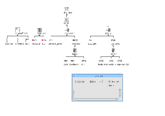
3. Check that you have the design shown in FIGURE 12-16.
It is a simple dialog consisting of two option menus, two toggles and a text field.
 [ D ]
[ D ]
4. Display the Generate dialog and choose "Motif XP" as the first language to generate.
Make sure that you have a target directory for the Motif-only sources.
5. Generate the Code file, Externs file, Main code file, Makefile and Stubs file. Use the names already shown in the Generate dialog.
You are going to overwrite the Stubs file with a pre-configured one, but you need X-Designer to create a dependency for it in the Makefile.
6. Change the "Language" to "MFC". Remember to change the target directory as well.
7. Generate the Code file, Externs file, Main code file and Windows Resource file but not the Stubs file.
You are going to use the same pre-configured Stubs file mentioned above, but you need X-Designer to create a dependency for it in the Visual C++ project files.
8. Copy over the following stubs file into your Motif XP directory:
$XDROOT/src/examples/mfc/singlesource_stubs.cpp
You will just need to remember to copy it over to your PC along with the MFC source you just generated.
You can look at the Stubs file in a text editor. There are three callbacks:
All of this code can be shared by the Motif XP application and the MFC application.
9. To compile the Motif application, simply make sure you are in your motif directory and type: make at the command prompt.
See Chapter 7 for more information on generating, compiling and running code.
10. Once it has built, run the application on Motif checking that your callbacks work. Try setting the two toggles and making selections from the option menus.
11. To build the MFC application:
a. Take all of the files generated into your MFC directory to your PC.
Remember to take the ".dsw" and the ".dsp" files, the Visual C++ project files.
b. Take the pre-configured Stubs file from the Motif XP directory to your PC, overwriting the first one, which was only generated to force the correct dependencies.
c. If you are not using Visual C++, see Using Other Applications for points to remember when compiling on your PC.
d. On your PC, open the ".dsw" file in Visual C++ as the project workspace.
This assumes you are using Visual C++ Version 5 or later. If you are using an earlier version or a different application, refer to Compiling the Microsoft Windows Version.
g. Check that your callbacks work--try setting the toggles and making selections from the option menus.
The XP Graphics Toolkit consists of a set of interface classes for drawing and toolkit primitives modelled on Java. These classes allow you to create a single set of source code for drawing and events on both Motif and Microsoft Windows in the same way you can already single source user interface code using the MotifXP libraries. You write code using this toolkit and the libraries translate it according to your target platform. The source code for these libraries is accessible, allowing you to add your own code if you should wish to provide extra functionality for certain widgets.
The following lines show a simple example of how the toolkit may be used:
Toolkit *tk = Toolkit::getDefaultToolkit(); Graphics *g = tk->getGraphics(drawingArea); g->drawLine(10,10,100,100); |
The graphics toolkit also encompasses double buffering and takes care of the slightly more complex issues of X and WIN32 GDI memory allocation issues that overcomplicate what should be simple drawing routines.
The toolkit can also handle abstract events with classes which remove any platform specifics regarding event driven interfaces. In exactly the same way as is shown for the line drawing example above, you could fetch the toolkit object and ask it for any outstanding events and process them generically in your own code. The XP Graphics toolkit libraries would then handle the specifics according to the toolkit you are targeting.
There are two other options you could consider for single sourcing of callback files:
The Java programming language gives you platform independence. X-Designer can generate your design in Java code. In addition, you can save your design in a format ready for importing into Visaj, the Java application builder. Chapter 10 explains all about creating Java applications from your design.
Get/Set Smart Code gives you a toolkit-independent "wrapper" around widgets that you are interested in. Full details, including a short tutorial, are given in Chapter 16.
Copyright © 2003, Sun Microsystems, Inc. All rights reserved.